
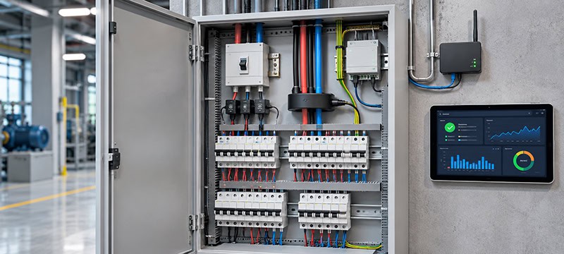
Smart Electrical Panels: A Guide to IoT Current Sensors and Monitoring
A typical version of the call comes on a Monday. A residual current breaker in a cold-storage warehouse tripped twice over the weekend, taking the compressors with it, and the facility manager wants to know why. The building has a “smart” distribution panel: a multifunction meter on the incomer, a gateway, and a cloud dashboard with tidy kilowatt-hour charts. None of it can say which circuit was leaking, how much, or whether the leakage had been creeping up for weeks.
That gap is common. Many panels sold as smart are really just metered. They see total energy and little about individual feeders, let alone small currents escaping to earth.
This guide looks at the main current-sensing technologies used in smart electrical distribution panels, explains why earth leakage needs a sensor of its own, and covers the other measurements that matter. It also follows the data from the terminal block to the cloud and outlines what to check before ordering hardware. The aim is that the next unexplained trip comes with an explanation attached.
Why Smart Distribution Panels Need More Than Energy Metering
A panel can run for twenty years without anyone opening the door, so the case for instrumenting it has to be concrete. Most often it comes from one of four places:
Energy visibility per circuit or tenant, for cost allocation or finding the HVAC unit that eats the budget.
Predictive maintenance, such as spotting a motor that draws more current than it did last quarter.
Electrical safety monitoring, mainly detecting insulation degradation and earth leakage, which can sometimes appear as a trend before causing a trip.
Remote operations at unstaffed sites, including telecom shelters, EV charging hubs and small retail stores.
All four rely heavily on current measurements. Voltage alone tells a limited story about how individual loads behave; current reveals changes in operating conditions and potential faults. In many Industrial IoT projects, current sensors end up determining the cost, accuracy and installation effort of the entire monitoring chain.
Five Current Sensing Technologies for Smart Electrical Panels
No single current sensor fits every point in a panel. Shunts, Hall-effect sensors, conventional current transformers (CTs) and Rogowski coils all measure load current, with different compromises on isolation, DC capability, bandwidth and size. Zero-sequence current transformers (ZCTs) do something else: they measure the imbalance across all live conductors, which is what earth leakage looks like electrically.
A shunt is a precise low-value resistor sitting in the power path, and the voltage across it tracks the current. The other technologies use magnetic effects to measure current without placing a resistive element in the main current path. Hall-effect sensors use a semiconductor element, conventional CTs rely on magnetic induction, and Rogowski coils use an air-cored winding that cannot saturate magnetically. Flexible Rogowski coils are therefore popular for wrapping around large busbars in retrofit installations.
The following table summarizes the main trade-offs.
Technology
What it measures best
Typical limitation
Common applications
Shunt resistor
AC and DC load current at low to moderate levels
No inherent galvanic isolation; heat dissipation at high current
Battery systems, DC distribution, compact meters
Hall-effect sensor
AC, DC and mixed-waveform currents
Offset and temperature drift; requires supply power
PV and battery inverters, EV chargers, DC feeders
Standard CT
AC load current at mains frequency
AC only; can saturate under excessive current or DC bias
Feeder and branch metering, tenant sub-billing
Rogowski coil
Large or fast-changing AC currents and harmonics
Requires an integrator; typically less suitable for very small currents
Large busbars, retrofits, power quality analysis
Zero-sequence CT (ZCT)
Small residual (earth-leakage) current across all live conductors
Does not measure individual load current; conventional types are AC-only
Earth-leakage monitoring, insulation trending, residual current protection systems
A real smart distribution panel rarely uses just one of these technologies. More often, it combines two or three of them to capture different electrical conditions.
Why a 400 A Current Transformer Cannot Reliably Detect a 30 mA Fault
A common assumption is that, since each phase already has a CT, software can add the phase and neutral currents and calculate the remaining leakage. On paper, that works. In a healthy circuit, the vector sum of the currents through all live conductors is zero. Current that does not return through those conductors may indicate a fault path to earth.
In practice, the arithmetic tends to fall apart. A 30 mA leakage on a 400 A feeder represents just 0.0075% of the CT’s rated current. Conventional metering CTs are not designed to resolve such small differences between large current measurements.
For example, a class 0.5 metering CT has a permitted current ratio error of 0.5% at rated current under specified conditions, equivalent to 2 A at 400 A. Accuracy limits also vary with the operating current, and errors typically increase at low percentages of rated current. With several sensors contributing measurement and phase errors, the calculated residual current can be dominated by sensor mismatch rather than actual leakage.
Teams attempting this approach may see apparent leakage rise every morning as building loads start up. That does not necessarily indicate failing insulation; it may simply reflect differences between the individual CT measurements.
This is the job zero-sequence current transformers (ZCTs) are built for. The phases and neutral pass together through a single magnetic core. Under balanced conditions, their magnetic effects cancel, and the sensor responds to the residual current. Because the core does not have to measure the full load current as its net signal, properly designed ZCTs can detect leakage in the milliamp range, with exact sensitivity depending on the model.
AC, DC and High-Frequency Leakage Currents
Not every leakage current is a clean mains-frequency sine wave. Variable-speed drives, EV chargers, PV inverters and switch-mode power supplies can produce residual currents containing pulsating DC, smooth DC or high-frequency components.
Residual current devices are categorized according to the fault-current waveforms they can detect, commonly using types AC, A, F and B. Sensor specifications do not always map directly onto these protection device categories, so it is important to check which residual current waveforms a sensor is actually designed to measure.
A conventional core-balance CT is primarily designed for AC residual current, and smooth DC components can impair its sensitivity. Installations with extensive power electronics may require alternative sensing principles, such as fluxgate technology, or dedicated residual current monitoring solutions.
Ultimately, the sensor’s specified residual current types, measurement range and frequency response determine whether it is suitable for the application.
There is also an important distinction between monitoring and protection. A residual current monitor reports measurements and raises alarms, while a residual current protective device disconnects the circuit when required. IoT-based leakage monitoring provides early warning and diagnostic information; it does not replace mandatory electrical protection.
Beyond Current: Temperature, Voltage and Other Smart Panel Sensors
Thermal surveys of older panels often reveal a terminal running hotter than its neighbours, sometimes because a connection has loosened through years of thermal cycling. The current sensor may see nothing unusual because the load has not changed. A temperature sensor positioned near the terminal or busbar joint can help identify the developing problem.
Some retrofit installations use wireless temperature sensors to avoid adding extensive measurement wiring inside the panel, although their installation and communication arrangements still need to meet electrical safety and environmental requirements.
Voltage measurements are equally important. Combined with current measurements and their phase relationships, they allow a metering module to calculate real power, apparent power, power factor and energy consumption.
Humidity sensors, arc detection systems and other environmental measurements can provide additional information, but their usefulness depends on the installation. Not every smart electrical panel needs every possible sensor.
Connecting Smart Panel Sensors to IoT Platforms
The most common architecture is also the least glamorous. Sensors feed a measurement module that computes RMS values, energy consumption and, where supported, residual current measurements. The module passes its readings over Modbus RTU on RS-485, a long-established industrial serial interface, to an edge gateway.
The gateway forwards selected measurements to an IoT platform, typically using MQTT or HTTPS over an IP network. It can also process measurements locally, filter routine samples and retain a detailed data window around an electrical event.
That local processing capability matters. Instead of transmitting every measurement continuously, an edge gateway can flag anomalies, trigger alerts and preserve the data needed to investigate a trip. The result is more actionable information without unnecessarily increasing communication traffic.
Choosing the Right IoT Connectivity
When a wired network is unavailable, wireless connectivity provides alternatives. LoRaWAN can be suitable for small, periodic measurements and alarm notifications, although its limited data rate and duty-cycle constraints can make large data transfers impractical.
NB-IoT provides cellular connectivity for relatively small data volumes, while LTE Cat 1 bis can support applications requiring greater throughput and more frequent communication.
The choice depends on reporting intervals, coverage, latency requirements, power availability and the volume of data to be exchanged.
Physical installation also matters. Metal electrical enclosures can significantly attenuate radio signals, so antenna placement and coverage testing should be considered early in the design. A gateway that communicates reliably with its enclosure open may not perform the same way once the cabinet is closed.
Securing the Smart Electrical Panel
Connecting electrical infrastructure to an IoT platform also introduces cybersecurity requirements. Gateways should support authenticated communications, encrypted data transmission where applicable, and controlled access to configuration and management interfaces.
Secure firmware updates, network segmentation and appropriate device lifecycle management can reduce the risk of unauthorized access or disruption. For operationally critical panels, monitoring and alerting should also remain effective during temporary cloud or network outages, with local data buffering and alarm handling where required.
How to Select Current Sensors for an IoT Distribution Panel
Many projects start with whichever CT is already available in the warehouse, only to discover later that it cannot detect small leakage currents or deliver the required accuracy across the operating range.
Accuracy class should match the intended purpose. Revenue-grade metering, operational trending and fault detection have different requirements. Measurement range deserves particular attention: a CT sized to the breaker rating may operate most of its life at a small fraction of its nominal current, so accuracy at the lower end can matter more than its headline specification.
Output type is another consideration. Conventional current-output CTs with 1 A or 5 A secondaries must not be left open-circuited while the primary circuit is energized. This is one reason some IoT monitoring installations prefer voltage-output or millivolt-output CTs, although compatibility with the measurement module and manufacturer installation requirements remains essential.
Residual current sensing introduces its own selection criteria. Sensitivity must be verified at the intended alarm threshold rather than inferred from the nominal sensor rating.
The sensor aperture must accommodate every live conductor belonging to the monitored circuit, including the neutral where present, while excluding the protective earth conductor. Conductor positioning also matters: significant asymmetry within the aperture can increase measurement errors, particularly at high load currents.
If variable-speed drives, chargers or inverters are connected downstream, an AC-only sensor may fail to capture relevant DC or high-frequency residual current components.
For reference, typical form factors and specifications can be found in the range of Zero Sequence Current Transformers.
Installation type is another trade-off. Split-core sensors allow retrofits without disconnecting existing cables, which can be decisive in occupied buildings. Closed-core sensors avoid the mechanical joint found in split-core designs, but generally require conductors to be disconnected or routed through the sensor during installation.
Neither construction is automatically more accurate at low currents. The specifications of the individual model, including its performance under expected operating conditions, are more important than the form factor alone.
Common Installation Mistakes That Can Undermine IoT Monitoring
Many field problems with current sensing turn out to be installation errors rather than sensor failures, and they may only become apparent once measurement data starts arriving.
Protective earth conductor routed through the residual current sensor. Fault current returning through the earth conductor can cancel part or all of the measured imbalance, preventing correct leakage detection.
Neutral left outside the sensor core. Normal load current then appears as residual current, potentially triggering an alarm immediately.
Load CT mounted backwards. Depending on the metering configuration, reversed polarity can produce negative power readings, making a consuming installation appear to be exporting energy.
Each of these mistakes can require an additional site visit costing many times the sensor’s purchase price. Correct installation, commissioning tests and validation against expected measurements are therefore essential parts of a reliable IoT monitoring deployment.
Smarter Electrical Monitoring Starts with Better Measurements
Smart electrical distribution panels will continue to gain new capabilities through edge analytics, cloud platforms and anomaly detection models trained on data from multiple installations. These technologies can help operators identify unusual patterns, prioritize maintenance and investigate electrical faults remotely.
But no software can recover information that was never captured in the first place.
The milliamps leaking through ageing insulation, the gradual warming of a terminal, or the DC component introduced by a new charger all require appropriate sensing technology.
Ultimately, whether an electrical panel is genuinely smart is still determined at the measurement point, long before its data reaches an IoT dashboard.
The post Smart Electrical Panels: A Guide to IoT Current Sensors and Monitoring appeared first on IoT Business News.